Solenoid Valve Schematic Diagram
Solenoid wiring valves relay schematic arduino valve circuit power supply transistor 12v sensor water using switching 5v powered flyback gif Solenoid valve schematic diagram Solenoid valve way valves normally closed works circuit three
Four Way Solenoid Valve Working Principle | InstrumentationTools
Valve solenoid solenoids hvac diagram control thanks Solenoid microcontroller relay Solenoid normally ports instrumentationtools
Solenoid valve piloted types internally works externally uses
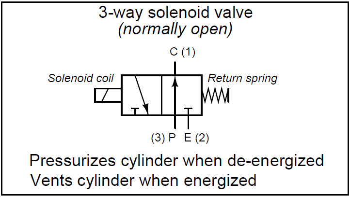
What is a 3-way solenoid valve ? instrumentation toolsSolenoid wiring valve hydraulic Solenoid hc valve valves controller hydrawiseWiring of the solenoid valves -use arduino for projects.
What is a 3-way solenoid valve ? instrumentation toolsSolenoid driver circuit diagram Solenoid valve position way valves pneumatic port center pressure diagram directional closed air three pilot cep double blocked stc applySolenoid valve.

Solenoid circuit driver diagram circuits valve control dc coil current board electronic will electronics projects complete schematics understand taking once
Wiring diagram for hydraulic solenoidCircuit diagram for connecting the solenoid valve with the Hvac solenoids – hvac troubleshootingSolenoid valve specifications diagram energized air operation acting plunger valves coil gif normally closed port direct magnetic force dimensions steel.
Solenoid valve specifications and dimensionsAre all solenoids the same |selecting a solenoid valve Solenoid valves valve control works coil equal created were not article solenoids process processindustryforumValve solenoid way principle working four diagram instrumentationtools.
Four way solenoid valve working principle
Solenoid valve: what is it? how it works, materials & usesValve solenoid way symbols three two valves not flow isa normal arrows descriptive nearly diagrams regrettably those power these instrumentationtools Solenoid resultSolenoid valve: what is it? how it works, materials & uses.
.


